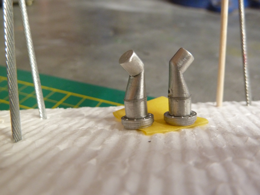
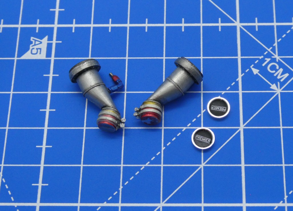
Fuel Filler Necks
For the fuel filler necks, I filed off the molded hose clamps and replaced them with photo-etched hose clamps and tiny screws. I painted in the red- and yellow-tinted fittings and covered with some clear het-shrink tube. Photo-etched weld beads were added as well. Both necks are molded with a hole for a pressure fitting, but there is only a fitting on the left hand side, so I have removed the molding on the right hand part. The centre caps have the brand name highlighted in flat white enamel, which came out better than last time, although I won’t install the caps until the necks are mounted on the body, so the orientation is correct.
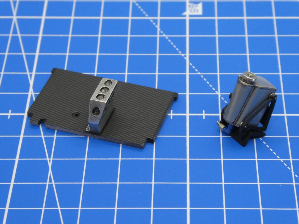
Water Fill Tank
For the fill tank for coolant (I think that”s what it is), the instructions are a little unclear about fittings on the left and bottom of the tank. From reference material we can see that:
- The bottom AN fitting doesn’t fit into the raised hole – that appears to be a cap or an electric plug, which I painted black and left alone. The AN fitting goes into the base of the tank immediately behind the molded hole – I say immediately as the fitting and hose needs to clear the framework around the tank.
- The fitting on the left side is (I think) a temperature sensor line, which I painted black and drilled for 0.4mm wire to be fit later. The clear yellow hose in the instructions goes into the tank just under the cap, I added a wire pin (nickel silver 0.4mm) to hold it.
- The tank cap sits at a jaunty angle just a little clock-wise of left-right across the body.
- The tank has weld beads around the top and bottom edges, and also vertically where the round part and the square parts join.